Wednesday, 10 December 2008

October Image Part Three

This is the third part of the Creation of the October Image. To create the body shape that will go under the Cloth I used Cylinders and Boxes that I then modified and placed them into the correct position. I had to create a rough look of a body to make the scene look more realistic and for the sheet to be placed over it. I then placed the body onto the operating table ready for the sheet to placed over it. I didn't need any textures on the body because it wont be seen.
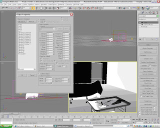


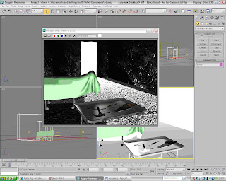
The next stage was to create the sheet that is going to be placed over the top of the body. I had to first create a rectangle that will become the sheet and convert to a poly. I then had to use the modifier called 'Garment Maker'. This is located in the drop down menu in the Modifier panel. This tool converts the rectangle into a material and allows the modifier 'Cloth' to be added to the rectangle. The 'Cloth' modifier is located in the same drop-down menu as the 'Garment Maker'. Once the 'Cloth' option has been the selected a menu panel appears at the right hand of the screen. This panel is used to create the cloth animation which will give the sheet its final look. Next you have to click on the 'Object Properties' Button which will load up a pop-up Menu called 'Object Properties'. You then have to add the body and the table which the sheet will lay over into the 'Objects in Simulation'. You then have to highlight all of the objects in this menu apart from the Sheet (Rectangle) and then click on the option 'Collision Object' which is a little check box. The next thing to do is to click on the sheet and then click on the check box named 'Cloth' located at the top of the screen. Now you have to click on OK and then click the button named 'Simulate Local'. The Simulation will now run and the Cloth will be placed over the body and the operating table.


This is what the cloth looked like when the animation was complete. The addition of the body under a cloth really adds to the mood of the image and creates a focal point for the audience observing it.
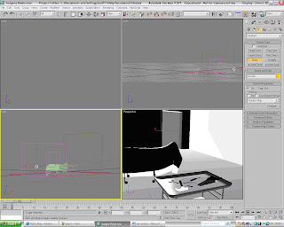


I then added some lighting to the scene to give the scene more atmosphere. I used a 'Target spot' for the light coming through the door way and I have also used some Omni lights to the scene. The picture below is the final rendered image of the October Image. All that is needed now is to transfer it into to photoshop and then add the finishing touches.
Tuesday, 9 December 2008

October Image Part 2

This is the second part of the creation of the October Image. The next step is to create the top of the table. I started off by creating a box which will be the main body of the tabletop. I made sure that when I created it I used lots of segments. I used about 15 for the each of the hieghts, Length and the width. This will then allow me to get the shape that I wanted for the table top. To get the curved edge I highlighted the edge of the the table and used the tool 'TurboSmooth'. This smoothed the edge to get the look that I wanted.


The next step was to add the texture to the table to give it more realism. I first found some textures off of the Internet and then transfered them into Adobe Photoshop. I then modifyed the Bitmap image and I then imported it into the Material Editor in 3Ds Max. I then transfered the material onto the Shapes that make up the Table. The Shader Basic Parameters that I used for the table materials was 'Metal'. This made the material look more like metal which was the look I was after.


The next stage of the October Image is to create the operating table where the body will be placed. The Body will have a sheet placed over it so that doesnt need to be much detail implemented into the table. To create the table I used the same technique that I used for the other table. I used cylinders for the legs and boxes for the actual surgery tabletop. The one difference of the operating table was to create wheels. I used cylinders that were rotatated and resized amd then moved into position. The wheels give the table more detail and make the image more interesting. I then added the same textures to the operating table as I have done for the other table.


The next stage of the Image is to create the tools that will be placed onto the table. I created them using Splines which I then extruded the shapes. This made them look more like 3D images and added to the dark feeling of the picture. I had some trouble when I created the handle of the Saw. To create the handle I first create the outline by using the spline 'Line' tool. I then converted it into a 'Poly' and then extruded the face. This made it look more 3D. The next step was to create the whole in the handle. To do this I had to use the tool 'ProBoolean' to cut out the shape. I first create a sphere and then placed inside the handle where I wanted the hole to be. I then selected the 'ProBoolean' tool located in the Compound Objects Menu at the right hand of the screen. I then Subtracted the Sphere from the Handle and this gave me the shape that I wanted. I then had to add the textures to the tools to make them look more realistic and make them look part of the scene.


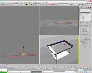
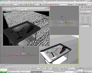
This is what the tools look like when they are fully rendered and with the Textures.

October Image Part One

This is the first part of the October Image Creation. October Image is a scene of a surgery that has been made scary. It is meant to look like some kind of scene from a horror movie. The first stage was to set the background color. For this image I will use the background color white. This will act as the color that appears through the doorway in the picture.


The next stage is to create the floor. I have used a box for the floor which I have resized to give the shape that I want. To make the floor look more realistic and more in charcter with scene I added a Cracked Concrete texture. I found this image on the internet and then imported it into my Material editor. To give the floor texture more depth I have also add the same texture onto the bump map which is located in the maps section of the Material editor. I then dragged the concrete texture onto the floor. When I intially did this the texture didnt give me the look that I was after. I had to attach a 'UVW map' to the floor which allowed me to modify the look of the texture.


The next stage was to add walls to the Surgery room. To create the walls I used the box creation tool which is located in the Create menu at the right hand of the screen. I then had to create the doorway which is going to be one of the main focal points of the scene. To create this door I had to use the tool called 'ProBoolean'. I had to first create a Box that is the shape of the doorway and then place it so that it was inside the wall. The box had to be wider than the wall to ensure the 'ProBoolean' tool would cut away the width of the wall. I then selected the wall and then went to the 'create' panel and I selected the 'Compound Objects' option from the drop-down menu. I then selected the 'Pro Boolean' option and then from the menu at the right hand of the screen clicked the check box named 'Subtraction'. I then clicked on the button 'Start Picking' and then selected the box. The box has now been subtracted from the wall. This gave me the look that I was looking for.


The next stage is to add texture to the walls. To do this I found an image of the internet and then edited in Adobe Photoshop. I then imported it into the Material Editor. I also used the same map for the bump map to give the walls more texture and the image more depth.


The next part of the creation of the October image is to create the metal table were the surgical instruments will be placed. I started out by creating the base of the table. To do this I used cylinders and then placed them to make the table look like it has a structure. I then created a box and then placed midway up the table and between the two sets of legs.


Final Summer Days Picnic Image

This is the Final Summers Day Picnic image
Summers Day Pinic Part Three

This is part three of the creation of the Summers Day Picnic 3D image for the month of July. All that needs to be created to finish the 3D image is the photos which will be scattered across the table. To create the photo I had to first select the create box tool and then I drew the photo onto the stage. I made this part white so that it looked like the outside of a poloriod photo. I then rotated and placed it onto the table. The placing of the photo was crucial to the overall look of the image. I didnt want the image to look too staged.


The next step was create the actual photo part of the photo. To do this I used a box which is slightly raised above the box which is used for the white part of the photo. I then duplictated the two boxes and then placed the clones onto the table next to the original. I rotated them so they looked scattered and not purposefully placed. To add images to boxes I first had to import the images into the material editor. The images were taken from the internet and then they were modifyed using the program Adobe Photoshop. The Material maps were then dragged onto the relevant boxes to give the look of real photos.


This is what the final rsult looks like with all of the maps added to give it the final look. All is needed now is to transfer this final image into Adobe Photoshop and add the finishing touches.

Summers Day Picnic Part 2


This is the second part of the creation of the Summers Day Picnic. I have now placed the glass onto the table and ensured that the table top texture looks correct. The glass will reflect the table top and the environment and make it look more realistic. The glass should reflect everything that is placed into the scene.


The next stage of the 3D image is to create the main body of the camara. To do this I will use a box and use the modifyer called 'TurboSmooth'. The 'TurboSmooth' modifyer can be found in the modiyer drop-down menu at the right hand of the screen. To ensure that the 'TurboSmooth' modifyer works correctly the box will have to have about 15 segments for the height, width and the length. As soon as the 'TurboSmooth' option has been clicked on the boxes edges will be smoothed. This makes the box look more realistic.


The next part was to create a box which will become the Flash. This will add more realistic look to the light. I first drew a box and then rotated it and placed it onto the main body of the camara. I then added the same texture to the Camara Flash as I did to the glass. This gave it that glass look.


I then had to create the main lense of the Camara. To do the first ring of the lense I used a cone which I then cut of the uppermost part. This gave me the effect that I wanted, which was a sloped beginning.


I then added the rest of the rings of the lense to the Camara. The rest of the rings where created using cylinders which resized and placed into position. I then added other cylinders onto the top of the camara to make them look like buttons and dials. This added to the Camara realism and look. To get the look of the dials and other aspects of the camara I used a picture a real camara obtained from the internet and then tried to copy it as much as possible. This hopefully made the final Camara look realistic and proffesional looking.

Summers Day Picnic Part 1

This is the first part of the creation of the 3D image Summers Day Picnic. I first started off opening up Autodesk 3Ds Max. I then set the background image called 'grass.bmp' which I had edited using the program Adobe Photoshop CS2. Setting the background image will help me create the image by being a starting point from which I can work from. The next step was to create a Cylinder to be the tabletop. I will create the other images later on in the development process. To create the cylinder I had to go to the 'create' menu and then selecting the cylinder option. With this selected I then drew the shape onto the stage. I then imported a texture map into the map editor and then dragged that onto the table top. This made it look more realistic and made it look more realistic.


The next stage in the Summers Day Picnic is to create the Glass. To create the glass I need to create a spline line. To do this I had to go to the 'create' menu and then select the spline tab. In this menu I then selected the line tool and drew a rough shape that I wanted. This shape will be used to lathe which will give me the final shape of my glass.


To lathe the line I first converted to the line into a poly. I then went to the modify menu located at the right hand of the screen and then scrolling down to the 'Lathe'. This option lathed the line so that the shape of the glass is created. The next stage of the creation of the glass is to add the material to make it look more like glass.


To access the material editor you can click on the material editor button which located at the top of the screen. The button looks like four different colour balls. To get the material for the glass I used the 'Phong' shading option and I then changed the Specular level to 250 and the glossiness to 80. This will give the glass a shine and gloss that looks more realistic. I have also added a 'Raytrace' map to the reflection map which will then give the surface of the glass a reflectiveness which resembles real glass.


Monday, 8 December 2008

Final Morning Dew Image

This is the final image for the month of May.